IEC 62353 Leakage Measurements
As discussed previously, it is the level of electrical current rather than level of voltage which is the criteria for safety due to the impact of electrical currents on the human tissues. Small amounts of current which are undetectable by sensation can have a significant impact on our safety.
IEC 62353 defines two different kinds of leakage current tests:
Equipment leakage current - total leakage deriving from the power supply to ground via the applied parts and enclosure (see Equipment Leakage).
Applied part leakage current - leakage current flowing from an applied part to the enclosure or ground as a result of an external voltage on the applied part (see Applied Part Leakage).
Method Characteristics
To ensure that a valid leakage measurement can be obtained, the IEC 62353 describes the following methods:
Direct Leakage - measurement of leakage current via a measuring device, placed directly in the path of the leakage current (see Direct Leakage).
Differential Leakage - measuring the imbalance between current in the live conductor and the neutral conductor as a result of leakage current (see Differential Leakage).
Alternative Method - measurement of leakage when mains voltage is both on the live and neutral wire (see Alternative Method).
Direct Leakage
The direct leakage method is identical to the method used in the IEC 60601-1 standard; measuring the true leakage through a body model (measuring device) to ground.
Benefits:
- Means of measuring both AC and DC leakage current.
- Highest accuracy compared to other methods.
- Potential leakage through a human body via measuring device.
- Direct comparison with measurements made in accordance with IEC 60601-1.
To consider:
- The 1kΩ resistor forming the measuring device is interrupting the low resistance protective ground conductor, thus causing a potential hazard when testing faulty equipment.
- Secondary ground path(s) could lead to zero current readings, see 8.4.
- A difference in polarity of the live and neutral conductors might alter the leakage readings, as such leakage measurements must be done in each polarity of mains supply.
- A TN (terre – neutral) system is required to ensure that the measurements are done at maximum live to ground voltage. Any voltage between neutral and ground might result in a lower reading, potentially passing faulty equipment, see 8.5
Differential Method
The differential leakage method measures the leakage current as a result of an imbalance in current between the live conductor and the neutral conductor.
The principle of the differential leakage measurement is based on induction hence, this method is susceptible to external magnetic fields and high load currents. As current passes through the live wire in one direction, the current in the natural wire travels in the opposite direction. Each current produces a magnetic field in opposite directions and directly proportional to the strength of current. See figure 17.
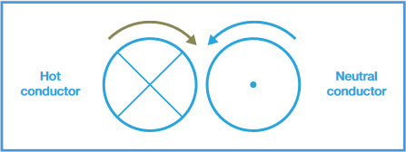
Fig. 17: Opposite magnetic fields in live & neutral wire
The current in the live wire carries both the functional current and the leakage current whereby the current in the neutral wire contains only the functional current. By subtracting both currents, you end up with the leakage current.
This is done in practise by passing both live and neutral wires through a current transformer (CT). The live and neutral wires act as the primary windings whereas the CT acts as the secondary winding. The net magnetic field in the primary wire is equal to the leakage current as the neutral “field” cancels all but the leakage current from the live wire. The current being inducted in the CT is equal to the leakage current.
Potential secondary ground connections are included in the total measurement and as such, the EUT is not required to be isolated from real ground.
Benefits:
- The measurements are not influenced by secondary ground connections.
- It measures the total equipment leakage current.
- The measuring device (1kΩ resistor) is no longer in series with the ground conductor, providing a low resistance protective ground and thus is a safer practise compared to the direct method.
To consider:
- The differential leakage measurement is less suitable to accurately measure lower leakage currents (<100µA).
- The measurements can be influenced by external magnetic fields or the analyser’s own internal magnetic fields.
- The measurements can be influenced by high current consumption of the DUT.
- The measurements have limited frequency response.
- A difference in polarity of the live and neutral conductors might alter the leakage readings; as such leakage measurements must be done in each polarity of mains supply.
- Both direct and alternative methods provide higher accuracy and broader frequency response which is required for measuring trends in low leakage conditions.
Alternative Method
The alternative method is in effect similar to a dielectric strength test at mains potential, or an insulation test at AC voltage, using a current limited voltage source (test voltage) at mains frequency. The maximum short circuit current is limited through a current limiting resistor of RL, see figure 18.
The live and neutral conductors are shorted together and the test voltage is applied between the mains parts and other parts of the equipment.
The current limiting resistor will result in an internal voltage drop when a fault current is flowing. Therefore, the applied test voltage will decrease when the leakage current increases.
To reflect testing at mains voltage, the measured leakage current is scaled in proportion to the actual output voltage. Note that IEC 62353 requires the safety analyser to show the “displayed value” and not the “measured value”.
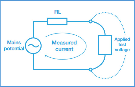
Fig. 18: Example of current limited mains supply during alternative leakage
IEC 62353 requires you to scale the measured leakage value up, equivalent to having mains over the applied part;
In this approach, it is possible to display high (calculated) leakage currents without actually being exposed to dangerous currents, making the alternative leakage current safe to use when high fault currents are expected.
Benefits:
- As live and neutral are combined, the mains polarity has no influence. Only one measurement is required.
- The DUT is disconnected from mains thus providing a high level of safety for the test engineer.
- TN-System is not required due to mains free application.
- Measurements are not influenced by secondary ground connections.
- Measurements are highly repeatable and provide a good indication of deterioration in the dielectrics of the medical device under test.
To consider:
- Equipment will not be activated thus, preventing the measurement of actual leakage currents on equipment with switched circuits
Equipment Leakage
Equipment leakage current - total leakage deriving from the power supply to ground via the applied parts and enclosure. The equipment leakage test is applicable to both class I and II, B, BF and CF equipment.
Leakage measurements to IEC 62353 are done using the RMS value instead of the separate AC and DC values used in the IEC 60601-1 standard.
The IEC 62353 specifies three different methods for measuring the equipment leakage current:
- Direct method
- Differential method
- Alternative method
Equipment Leakage Direct Method
The direct method is identical to the method used in the IEC 60601-1.
Figure 19 and figure 20 show a representation of the direct method.

Fig. 19: Equipment leakage direct - class I

Fig. 20: Equipment leakage direct - class II
The DUT must be positioned floating to avoid secondary ground connections influencing the measuring process.
All applied parts (B, BF & CF) and grounded (e.g. enclosure class I) and non-grounded accessible conductive parts or non-conductive accessible parts (enclosure class II) are grouped together and connected to the ground via the 1kΩ measuring device (body model).
The 1kΩ measuring device (MD - equivalent to that used in the IEC 60601 standard) is positioned in the leakage return path to ground.
The test is conducted with the protective ground connection ‘interrupted’, to ensure the measurements are carried out under the worst possible conditions. As such, any ground leakage current will be measured as part of the enclosure (or touch) leakage.
Measurements are done in both polarities of the incoming mains with the protective ground to the EUT interrupted.
|
Current in µA (RMS) |
APPLIED PART |
||
|
B |
BF |
CF |
|
|
Equipment leakage – direct or differential method |
|||
|
Class I equipment Class II equipment (touch current) |
500µA 100µA |
500µA 100µA |
500µA 100µA |
|
For mobile x-ray generators |
2000 µA |
||
Equipment Leakage Differential Method
Figure 21 and figure 22 show a representation of the differential method.

Fig. 21: Equipment leakage differential class I

Fig. 22: Equipment leakage differential class II
Potential secondary ground connections are included in the total measurement and as such, the DUT is not required to be positioned isolated from ground.
All applied parts (B / BF & CF), grounded (e.g. enclosure class I) and non-grounded accessible conductive parts or non-conductive accessible parts (enclosure Class II) are grouped together and connected to ground to allow the differential circuit to measure the total leakage current.
Unlike the direct method, the differential method does not measure the ground conductor via the standard IEC 60601 body model. The MD is part of a differential current measurement between the live and neutral conductors. The frequency response of the measurement shall be similar to the body model used in the IEC 60601. The test is conducted with the protective ground connection closed for protection of the user. Measurements are done in both polarities of the incoming mains with the protective ground to the EUT interrupted.
Low leakage currents of less than 75µA are difficult to measure using the differential leakage method. As such the differential leakage method is unsuitable when measuring conductive un- grounded parts and in instances where leakages are expected to be below 75µA.
|
Current in µA (RMS) |
APPLIED PART |
||
|
B |
BF |
CF |
|
|
Equipment leakage – direct or differential method |
|||
|
Class I equipment Class II equipment (touch current) |
500µA 100µA |
500µA 100µA |
500µA 100µA |
|
For mobile x-ray generators |
2000 µA |
||
Equipment Leakage Alternative Method
This method is in fact similar to a dielectric test between the mains parts and all accessible parts (conductive and non-conductive) including the applied parts connected together.
Figure 23 and figure 24 show a representation of the alternative method.

Fig. 23: Equipment leakage alternative - class I
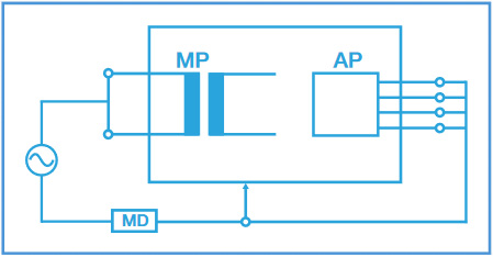
Fig. 24: Equipment leakage alternative - class II
The test is performed using a current limited (3.5mA) mains potential sinusoidal 60Hz signal (50Hz where this is the mains frequency). As live and neutral are shortened, the DUT is not directly connected to the mains potential. As such, mains reversal is not applicable and the EUT is not required to be positioned isolated from ground.
All applied parts, and grounded (e.g. enclosure class I) and non-grounded accessible conductive parts or non-conductive accessible parts (enclosure class II) are grouped together and connected to the mains parts via the 1kΩ measuring device (body model) and voltage source.
The 1kΩ measuring device (equivalent to that used in the IEC 60601 standard) is positioned directly after the voltage source. The test is conducted with the protective ground connection closed to protect the user.
|
Current in µA (RMS) |
APPLIED PART |
||
|
B |
BF |
CF |
|
|
Equipment leakage – alternative method |
|||
|
Class I equipment Class II equipment |
1000µA 500µA |
1000µA 500µA |
1000µA 500µA |
|
For mobile x-ray generators |
5000 µA |
||
Applied Part Leakage
The applied part leakage test measures the total leakage deriving from the combined patient connections within an applied art to ground and any conductive or non-conductive parts on the enclosure (either connected or isolated from ground) under the fault condition mains on the applied parts.
The applied part leakage test is applicable to floating type (BF & CF) applied parts only either class I or II.
All patient connections of a single function within an applied part shall be connected together (BF & CF) and measured one at the time. Applied parts (and patient connections) are not part of the measurement and shall be left floating i.e. not connected to real ground.
The test is conducted by applying a current limited (3.5mA) mains potential sinusoidal 60Hz signal (50Hz where this is the mains frequency) between the applied part, the enclosure and ground connection of the EUT that is connected to real ground.
Leakage measurements to IEC 62353 are done using the RMS value instead of the separate AC and DC values used in the IEC 60601-1 standard.
The IEC 62353 / applied part leakage can be performed in two different methods:
- Direct method
- Alternative method
Applied Part Leakage Direct Method
Figure 25 and figure 26 show a representation of the direct method.
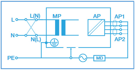
Fig. 25: Applied part leakage direct class I

Fig. 26: Applied part leakage direct class II
The DUT must be positioned floating to avoid secondary ground connections influencing the measuring process. All floating type patient connections in each applied part (BF & CF) are connected together. Each Individual applied part is measured in turn and grouped together with all grounded (e.g. enclosure class I) and non-grounded accessible conductive parts or non-conductive accessible parts (enclosure class II) and connected to ground via the 1kΩ measuring device (body model). Applied parts and patient connections not part of the measurement shall be left floating.
The 1kΩ measuring device (MD - equivalent to that used in the IEC 60601 standard) is positioned between the applied part and voltage source.
The test is conducted with the protective ground connection closed for protection of the user.
Measurements are done in both polarities of the incoming mains with the protective ground to the EUT interrupted.
Warning: This applied part direct leakage test is similar to that of the F-Type leakage test according to IEC 60601, using an equivalent current limited voltage source to produce the mains potential. Both sources depend on a current limiting resistor which could cause a significant voltage drop. See figure 18.
Unlike the IEC 60601-1 requirements, the voltage drop caused by the current limiting resistor is compensated for in the IEC 62353 thus, potentially resulting in a higher reading than the typical IEC 60601-1 F-type test. Please refer to the manufacturer’s recommendations.
|
Current in µA (RMS) |
APPLIED PART |
||
|
B |
BF |
CF |
|
|
Applied part leakage current – direct method (a.c.) |
|||
|
Class I & II |
N/A |
5000µA |
50µA |
|
For defibrillation paddles class CF |
N/A |
100µA |
|
Applied Part Leakage Alternate Method
This method is in fact similar to a dielectric test between the applied part, and all mains parts, EUT ground and enclosure all connected together. Figures 27 and 28 show a representation of the alternative method.

Fig. 27: Applied part leakage alternative – class I

Fig. 28: Applied part leakage alternative – class II
As live and neutral are shortened, the DUT is not directly connected to the mains potential. As such, mains reversal is not applicable and the EUT is not required to be positioned isolated from ground.
All floating type patient connections in each applied part (BF & CF) are connected together. Each individual applied part is measured in turn and connected via the 1kΩ measuring device (body model) to the voltage source and grounded (e.g. enclosure class I) and non-grounded accessible conductive parts or non-conductive accessible parts (enclosure class II) grouped together.
Applied parts and patient connections not part of the measurement shall be left floating.
The 1kΩ measuring device (MD - equivalent to that used in the IEC 60601 standard) is positioned between the applied part and voltage source.
The test is conducted with the protective ground connection closed to protect the user.
|
Current in µA (RMS) |
APPLIED PART |
||
|
B |
BF |
CF |
|
|
Applied part leakage current – alternative method (a.c.) |
|||
|
Class I & II |
N/A |
5000µA |
50µA |
|
For defibrillation paddles class CF |
N/A |
N/A |
100µA |
Secondary Ground Problems
Due to the fact that electrical currents follow the path of least resistance (much like water does), it is important to realise that secondary ground path connections could influence the measurements of leakage currents.
Secondary connections are typical with:
- Equipment bolted to steel reinforced concrete floor (e.g. dentist chairs, MRI)
- Equipment connected to gas or water supply
- Equipment that is part of a medical electrical system
- Equipment connected to PC / printer
Compared to the 1kΩ resistance of the body model, a secondary ground path is substantially lower. As such, electrical currents are mostly flowing down the secondary ground path, away from the safety analyser, as shown in figure 29, which represents an example of a secondary ground connection via a data cable.
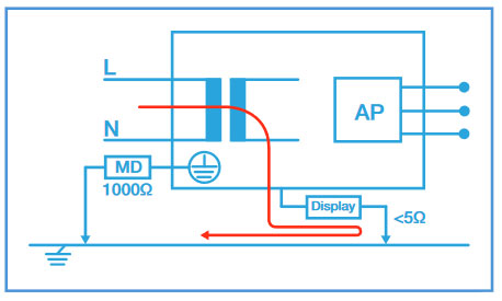
Fig. 29: Example showing leakage current flowing away via a secondary ground connection
This will result in a zero reading on the safety analyser and could potentially pass a dangerous medical device. In case a secondary ground path exists, the Rigel 288 / 62353 will provide the user with an error message as shown in figure 30.

Fig. 30: Secondary ground path errormessage on Rigel 288 / 62353
If the secondary ground path can’t be removed, one should revert to the differential leakage method which is capable of measuring the total leakage even when a secondary ground path exists. This is because the differential leakage method does not rely on a 1kΩ body model. See Fig 31.

Fig. 31: Measuring leakage current withsecondary ground using differential method
Live Conductor to Ground Voltage
During equipment leakage measurements (direct and differential), the live conductor to ground voltage can have a direct impact on the leakage measurement. In general, the smaller the live to ground voltage, the lower the leakage current to ground (leakage current flows from a high – live to a low – ground potential).
Measurements under a TN (terre – neutral) system ensure the live to ground voltage is equal to the line voltage (between live and neutral). This gives the highest possible leakage outcome, see figure 32. If the ground potential differs from the neutral potential, the live to ground voltage will be reduced, and result in a lower leakage value, see figure 33.

Fig. 32: Leakage measurement on a TN system
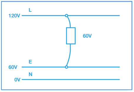
Fig. 33: Leakage measurement on a IT system
Leakage current measurements on an IT (isolated terre) are limited to isolation levels of the supply system. In this case, no valid leakage measurement is possible unless the safety analyser is able to produce an internal ground at half the line voltage, like the Rigel 288. It is also possible to test using the equipment leakage using the alternative method which does not rely on the incoming mains configuration.
The Rigel 288 and 62353 are able to provide an automatic warning to the user in case the supply configuration differs from a TN configuration. See Fig 34.

Fig. 34: Automatic mains configuration warning on Rigel 288 / 62353


