Insulation Resistance Test
The risk of unacceptably high electrical fault currents can be minimized through design criteria i.e. through effective levels of electrical insulation/isolation. Such insulation can be achieved through physical spacing (creepage and clearance) of components, choice of components and dielectric materials, while ensuring the device operates properly.
The effectiveness of electrical insulation is tested through electrical leakage measurements (results in mA or µA) while the level of isolation is often tested using a dielectric or insulation test. During a dielectric, or hipot test, a high voltage (up to 4000V AC) is applied across different parts of the electronic design in order to stress the dielectrics. Results are displayed in mA or µA - similar to that of leakage current measurements. An insulation resistance test applies a lower DC voltage, typically between 250-500V DC, across different parts of the electronic design. The results are displayed in Mega ohms (MΩ).
Insulation resistance is normally checked by applying 500V DC between:
- Input (live conductors, both phase and neutral, connected together) and enclosure (protective ground in class 1).
See Insulation Resistance EUT to Ground. - Output (applied parts) and enclosure (Protective ground in class 1).
See Insulation Resistance Applied Parts. - Input (phase and neutral) and output (applied parts) for floating type applied parts (BF and CF).
See Insulation Resistance Applied Parts to Mains.
The resistance is measured and then compared with the minimum acceptable value to assess pass or fail conditions, which can vary greatly depending on design and test voltage variations.
With all measurements of insulation resistance, the appliance under test must have the power switch in the ‘ON’ position before performing the test otherwise the test voltage does not pass beyond the mains switch, in which case only the mains cord will be tested.
In addition, appliances fitted with electronic mains switches or RCD plugs cannot be tested in this manner because it is not possible to close the mains switch (as they require mains to be present).
In some cases, sensitive electronic devices and particularly older IT equipment, which does not comply with EN60950, may be damaged by 500V. However, in practice, this may not be a significant issue as EN 60950 has been around longer than most IT equipment currently in use.
While the outcome of a 500V DC insulation test is quick and safe to do, in most cases it does not provide a real indication of the effectiveness of the insulation in modern medical devices or the expected leakage values that may be experienced during normal or typical operation. This is due to the increased use of switch mode power supplies that may indicate very high DC insulation resistance (>100MΩ), when measured with AC indicate high leakage. This is due to the greater influence of capacitive and inductive leakage experienced in these devices rather than resistive leakage as in a heating element.
Infinity readings are common when performing DC insulation tests and provide no information as to whether the unit was actually switched on or off. This makes the test results meaningless from a safety point of view.
It is a matter of debate as to whether a 50 MO (higher) result is ‘safer’ than a 10 MΩ (lower) result, considering the equipment has been exposed to a voltage it was not designed to operate at. Furthermore, the 50 MΩ (higher) device might have been designed to measure 100 MΩ and has thus lost 50% of its insulation level. This could lead to higher leakage currents and unsafe conditions.
Finally, in some electrical equipment, components connected to the live/neutral conductors for EMC filtering or surge protection can significantly influence the measurement, indicating an erroneous failure of the test. On the plus side, the insulation resistance test is relatively quick and easy to perform, which is why it is probably the most widely used.
Insulation Resistance EUT to Ground
This test is used to verify that the mains parts are adequately insulated from ground (class I) or the enclosure (class II). Figures 12 and 13 below, show a representation of the insulation test.

Figure 12: Insulation test mains parts to protective ground, class I

Figure 13: Insulation test mains parts to non-grounded accessible conductive parts, class I and II
Note: During this test, 500V D.C. is applied between the ground pin and both the live and neutral pins of the appliance mains supply plug.
For both class I and class II appliances plug the DUT into the safety analyser. Class II equipment requires an auxiliary lead to be connected to the enclosure of the equipment. This can be done by wrapping the enclosure in aluminium foil and connecting it to the auxiliary lead via a crocodile clip.
Insulation Resistance Applied Parts
This test is used to verify that the applied parts are adequately insulated from ground (class I) or the enclosure (class II). This test is applicable to class I and class II, BF and CF equipment only. Figure 14 and figure 15 show a representation of this insulation test.

Figure 14: Insulation test applied parts to protective ground, class I

Figure 15: Insulation test applied parts to non-grounded accessible conductive parts, class I and II
Note: During this test, 500V D.C. is applied between the ground pin (class I) or the enclosure (class II) and all the applied parts combined.
For both class I and class II appliances, connect the patient connections or applied parts to the corresponding terminals of your safety analyser. For class I equipment, plug the mains plug into the safety analyser. Class II equipment requires an auxiliary lead to be connected to the enclosure of the equipment. This can be done by wrapping the enclosure in aluminium foil and connecting the auxiliary lead via an alligator clip.
Insulation Resistance Applied Parts to Mains
This test is used to verify that the applied parts are adequately insulated from the mains parts and is applicable to class I and class II, BF and CF equipment only. Figure 16 show a representation of the applied parts to mains Insulation test.
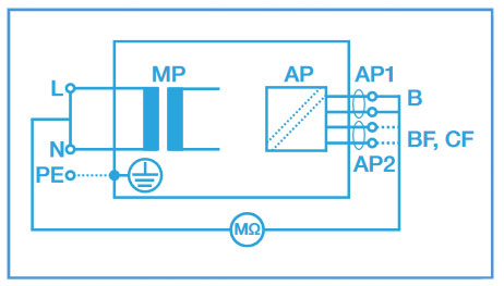
Figure 16: Insulation test mains parts to applied parts, class I and II
Note: During this test, 500V D.C. is applied between all the applied parts combined and both the live and neutral pins of the appliance mains supply plug.
For both class I and class II appliances, connect the patient connections or applied parts to the corresponding terminals of your safety analyser and connect the mains plug to the safety analyser.
Insulation Test Pass Fail Limits
Although ultimately the pass / fail limits or expected minimum values for this test must be advised by the manufacturer of the equipment, the IEC 62353 does provide a list of commonly accepted values:
|
Figure |
Class |
B |
BF |
CF |
|
Figure 12 |
I |
≥ 2 MΩ |
≥ 2 MΩ |
≥ 2 MΩ |
|
Figure 13 |
I and II |
≥ 7 MΩ |
≥ 7 MΩ |
≥ 7 MΩ |
|
Figure 14 |
I and II |
≥ 70 MΩ |
≥ 70 MΩ |
≥ 70 MΩ |
|
Figure 15 |
I and II |
≥ 70 MΩ |
≥ 70 MΩ |
≥ 70 MΩ |
|
Figure 16 |
I |
≥ 2 MΩ |
≥ 70 MΩ |
≥ 70 MΩ |
|
Figure 16 |
II |
≥ 7 MΩ |
≥ 70 MΩ |
≥ 70 MΩ |